 Reading time: 12 min
What Is a Surge Vessel?
A Surge Vessel, or pressurized surge vessel also called hydropneumatic tanks, injects water into the flow path under pressure when negative pressure waves occur in the pipeline. In this way, the formation of water column separation is prevented. On the other hand, when pressure rises due to water hammer, the tank acts as a cushion and absorbs the excess pressure. This causes the pressure rise to decay gradually and be eliminated.
1- How a Pressurized Surge Vessel Works?
In practical operation, the system relies on the dynamic interaction between the water and the compressed air inside the vessel. In other words, these tanks work in such a way that when the driving force of the pump is cut and, as a result, the volumetric flow rate decreases, the compressed air inside the tank forces water into the discharge line. This reduces the effects of the shutdown.
On the other hand, after a short time, the water in the discharge line comes to rest and then reverses direction. The water then flows back into the tank chamber. In this state, the air inside the tank is compressed and its volume decreases. This eliminates and reduces the excess pressure caused by water hammer.

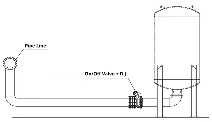
Figure 1: Schematic of a pressurized Surge Vessel connected to a pipeline
2- General Points in the Design of a Pressurized Surge Vessel
A Surge Vessel, also called a surge vessel or air chamber, is the most reliable device for controlling water hammer in both pressure-rise and pressure-drop conditions. Its need for compressed air supply equipment and its high maintenance cost are among its drawbacks. In the design of a pressurized Surge Vessel there are certain points, which we briefly present here. These points are taken into consideration by this company in design and manufacturing.
Accurately calculating the amount of water and air in a Surge Vessel is very important. Sometimes design engineers, without performing a proper transient analysis and without accurate calculation, fill half of the tank with water and the rest with air. In reality, the correct ratio depends entirely on the unique hydraulic characteristics and transient behavior of the system.
The amount of water or air inside the tank is directly related to the nature of the water hammer phenomenon. For example, where water column separation is severe and more water must be discharged into the line, the water volume of the tank must also be greater. This provides adequate protection under transient conditions. Accurate sizing generally requires transient analysis and careful examination of the pipeline profile.
Without relatively accurate calculation in the project planning stages and a detailed study of the line profile, the Surge Vessel volume cannot be estimated for a project by any means. This point is very important, especially for engineers who intend to avoid calculation in tenders! The tank volume depends on many parameters, including the type of profile and elevation changes, diameter, flow rate, pressure, air valves, and the moment of inertia of the pump. Each of these parameters can increase or decrease the tank volume.
The diameter of the pipe for flow into and out of the tank is very important, and its calculations must be completely accurate to ensure correct hydraulic performance.
⚠️ Warning – Undersized Connection Piping:
If the connection piping is too small, the Surge Vessel cannot exchange water with the pipeline fast enough. This severely reduces its effectiveness during transient events.
Given the complexities and subtleties of water hammer calculations and pressurized Surge Vessel design, it is necessary to use computer software in the calculations, observing all technical and practical points, so that the results have acceptable accuracy and the extra costs of overestimating or underestimating dimensions and specifications in the design are avoided.
The most common and most accurate standard used in the design of pressurized Surge Vessels is the ASME Pressure Vessel Code (the standard of the American Society of Mechanical Engineers), which is regularly updated. This standard is the best-known global standard in pressure vessel engineering, and this company uses it.
3- Installation (Placement) of the Surge Vessel
A Surge Vessel is built as a cylinder with two heads. Depending on the layout of the pumping station and the surrounding structures, it can be placed in pumping stations and other parts of the project in three forms:
- Vertical (upright)
- Inclined
- Horizontal
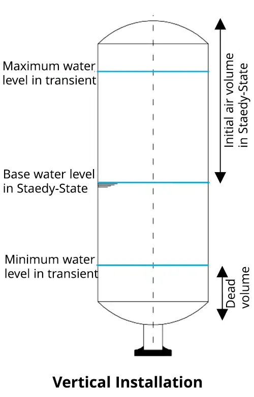
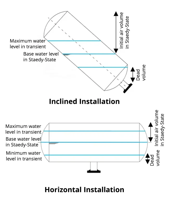
The most common and best arrangement for a Surge Vessel is vertical. Among the disadvantages of placing tanks horizontally is the increase in unused, hydraulically inactive water volume (dead volume) in the tank, and therefore the total tank volume must be considered larger. In inclined placement, the problem of increased unused water volume is partly resolved, but there are problems with the tank supports, maintenance, anchoring, and long-term stability.
💡 Tip – Prefer Vertical Orientation:
Where space and structure allow, choose vertical installation. This minimizes dead volume, reduces the required tank size, and simplifies the support and anchoring details.
4- Surge Vessel Material
Overall, after performing the calculations in the software and determining the initial air volume, the expanded air volume, and the dead volume, the final tank volume is obtained. Then, according to the installation space and the available facilities, the diameter and height are determined. Based on the calculated diameter and height, and according to the ASME standard and the plate material, the steel plate thickness is also obtained.
According to the ASME standard and based on experience, the plate material of pressure vessels for pressures below 10 bar is ordinary ST-37 steel, and A516-Gr70 is used for higher pressures. Overall, given the small price difference, this company recommends using A516-Gr70 steel plate at all working pressures to guarantee improved structural reliability.
5- Inspection Opening (Manhole)
For internal inspection and for painting and coating work inside the tanks, pressurized Surge Vessels must have a manhole. The usual size requirements are:
- Tanks with a diameter greater than 1.5 m: a manhole with a minimum diameter of 450 mm
- Tanks with a diameter smaller than 1.5 m: a manhole with a minimum diameter of 400 mm
During operation, the manhole opening is normally securely closed with a blind flange to maintain pressure integrity.
6- Compressed Air Required for the Surge Vessel
The air compressor is responsible for supplying the air needed in the Surge Vessel under steady-state conditions. At the start of operation of the Surge Vessel facility, the air compressor must be brought into service after the electric pumps are turned on and continuous flow is established, and it supplies the initial air volume. During operation as well, because part of the trapped air gradually dissolves in the water and air leaks may occur, the compressor must be started periodically and the initial air volume adjusted. Therefore, the volume of air that the compressor must supply is the same as the air volume of the Surge Vessel under steady flow conditions.
The compressed air supplied by the air compressor under steady flow is delivered to the Surge Vessel by the following two methods:
Direct Air Injection into the Tank
In this case, the compressor outlet pipe, after a safety valve, a check valve, and a ball on-off valve are connected, is connected directly to the upper part of the Surge Vessel. When compressed air is needed in the Surge Vessel and the water level must be adjusted, the compressor starts and feeds compressed air directly into the tank. As a result, the water level is adjusted.
Using a Compressed Air Storage Tank
In this case, the compressed air is supplied by the compressor and kept in a separate air storage tank. This tank is filled automatically with the help of a pressure switch installed on the storage tank; in this way, the air pressure in the storage tank is always kept constant. The outlet of the storage tank, after a check valve and a ball on-off valve and, if necessary, a solenoid valve are installed, is connected to the upper part of the Surge Vessel.
When air must be injected into the Surge Vessel and the water level adjusted, the ball on-off valve or the solenoid valve connecting the air storage tank and the Surge Vessel opens. In this case, the air required for the Surge Vessel is supplied, allowing compressed air to enter the Surge Vessel and the desired water level to be restored.
7- Water Level Control in the Surge Vessel
In a Surge Vessel, several methods are used to monitor and control the water level (or the initial air volume), as follows:
Sight Glass Pipe:
If a sight glass pipe is used, it is not possible to use automatic water-level start-up and adjustment systems from the control room. In addition, it is made of glass, and the likelihood of it being damaged or broken in the pumping station environment is high.
Water Level Sensor:
Given the importance of controlling the water and air level in the Surge Vessel, for continuous control, level sensors must be installed at no fewer than four points, and they adjust the Surge Vessel water level by automatic command.
Magnetic Level Indicator:
In this method, an electromagnetic gauge is installed on the tank. This gauge consists of a vertical rod, and a float that slides on the rod rests on the water surface. A magnet is provided inside the float, and as it moves along the vertical rod, which contains electrical coils, induction occurs.
In this way, the water level can be observed as a weak current at the gauge output. This method is the most suitable and most cost-effective way of controlling the water level in the tank.

8- Connection of the Surge Vessel to the Pipeline
The Surge Vessel is connected to the water transmission pipeline through a nozzle provided at the bottom of the tank. During the fabrication of the Surge Vessel, the water discharge connecting pipe, together with a flange with a working pressure suited to the system, is provided on it. In general, there are two methods for connecting the Surge Vessel to the transmission pipeline:
Connection of the Surge Vessel with Bypass
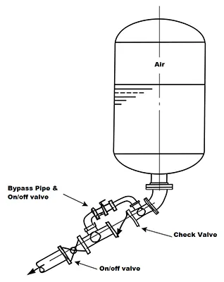
In order to damp the transient flow in the transmission pipeline more quickly during water hammer, a check valve is usually used on the main connecting pipe between the Surge Vessel and the pipeline, and in parallel with it a smaller-diameter bypass equipped with an orifice is provided.
In this case, when negative pressure occurs, water flows into the pipeline through the larger-diameter main connecting pipe. When positive pressure occurs and the direction of water flow changes from the pipeline toward the air chamber, the check valve closes and the water passes through the bypass equipped with an orifice. This path has a greater pressure loss than the main path, and this pressure loss plays an effective role in the rapid damping of water hammer waves.
Connection of the Surge Vessel without Bypass
In small pumping stations and in Surge Vessels with volumes of about 3 cubic meters or less, the bypass at the outlet of the pressurized Surge Vessel is usually omitted, and an orifice condition is considered at the connection opening of the tank's outlet pipe. In projects where the hydraulic pressure is less than 10 bar and the rapid damping of the water hammer flow does not play a decisive role, the orifice and local pressure loss are usually not included in the tank either.
Based on this company's experience in various projects, given the frequent failures of check valves, the probability of the Surge Vessel going out of service when connected with a bypass pipe is very high. Therefore, it is recommended that a connection without bypass be used at all working pressures, and that, if positive pressures need to be reduced, an orifice be used at the tank outlet opening.
✅ Best Practice – Direct Connection:
For most applications, a direct connection with a properly sized orifice is more reliable than a bypass with a check valve. Fewer moving parts generally means higher availability and less maintenance.
9- Conclusion
Surge Vessels are a proven and highly effective method for controlling transient pressure fluctuations in pipeline and pumping systems. By using a controlled air cushion inside the tank, they reduce the intensity of water hammer, protect valuable equipment, and improve the long-term reliability of the system.
To achieve optimal performance, the sizing and configuration of the Surge Vessel must be based on accurate transient analysis, realistic operating scenarios, and reliable instrumentation.
10- Professional Consultation KEG
Selecting the appropriate type, size, and installation location of a Surge Vessel requires careful evaluation of the operating conditions and possible transient events. Kavir Engineering Group provides specialized engineering consultation, transient analysis support, and complete guidance on the design and manufacture of Surge Vessels for pumping stations and pipeline systems.
To review the specific requirements of your project and receive technical recommendations, please prepare the following information. After receiving the information, the group will provide a preliminary configuration and a description of the inputs required for the final transient analysis.
Minimum Inputs (Checklist):
- Pipeline length, diameter, material, and wall thickness (or SDR)
- Elevation profile (high points and low points)
- Steady flow rate and working pressure
- Pump type, rated curve, inertia and shutdown or power-failure (pump trip) scenarios
- Valve types and their closing/opening times (if any)
- Existing surge control equipment (air valves, PRV, VFD, flywheel, etc.)
- Allowable pressure range (minimum/maximum) and design code (ASME / PED)
Typical Deliverables:
- Recommended Surge Vessel arrangement (with or without bypass, orifice type)
- Initial volume range and sizing assumptions
- List of additional data required to verify the final design