
What Is Water Hammer and What Causes It?
You may have heard the term water hammer without fully understanding the physical process behind it. Other expressions such as hydraulic shock, pressure surge, and surge are also commonly used.
The name (water hammer) derives from the distinctive and often violent noise produced during the event, similar to a heavy hammer striking a metal pipe.
From an engineering standpoint, water hammer occurs when a moving fluid is forced to stop or change direction abruptly in a pressurized pipeline. In essence, this phenomenon represents a major energy transformation, where the kinetic energy of the flowing fluid is converted into elastic strain energy within both the fluid and the pipe wall.
Under steady state conditions, fluid flowing inside a pipe possesses two primary forms of energy:
- Kinetic energy, represented by flow velocity
- Potential energy, represented by internal pressure
According to Bernoulli’s principle (neglecting minor friction losses), the sum of these energy components remains constant. The problem begins when a transient event occurs—i.e., when flow velocity changes abruptly.
When velocity is suddenly reduced, the fluid’s kinetic energy has no gradual path for dissipation and is instantaneously converted into pressure energy. This manifests as a sudden pressure rise, stored elastically through fluid compression and pipe wall expansion. These fast moving, damped pressure waves are not limited to pumping stations and can occur in any pipeline—whether gravity pipelines or pumped.
In extreme cases, the destructive power of these pressure waves, which depend on time and flow rate variation, can threaten entire water infrastructure systems, from water tunnels to oil transmission pipelines.
1. Where Does Water Hammer Occur?
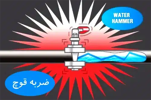
In pressurized hydraulic systems such as water and oil transmission pipelines, water distribution networks, hydraulic tunnels, pumping systems, and gravity pipelines, water hammer generates rapid, short lived pressure waves that pose serious risks. Typical consequences include:
- Pipeline rupture in transmission and distribution systems
- Pipe crumpling and internal corrosion
- Failure of valves, control devices, and pumps
2. What Triggers Water Hammer?
Water hammer is caused by a sudden interruption, reduction, or increase in fluid velocity within a closed conduit. Pressure fluctuations—both positive and negative—are directly generated by changes in flow velocity. Common triggering events include:
- Rapid opening or closing of valves
- Sudden pump start up or unexpected power failure (pump trip)
- Pipe rupture or sudden leakage
- Water column separation
Pro Note: Preventing water hammer does not simply mean using thicker or heavier pipes. The key lies in momentum management. Since transient overpressures are directly proportional to velocity changes, effective surge control strategies are designed to slow down rapid velocity transitions.
3. Effects and Consequences: Why Is Water Hammer Critical?
Although transmission pipelines—both gravity pipeline and pumped—are designed based on steady state flow conditions, such conditions are rarely maintained in practice. Sudden operational changes lead to transient and unstable flows. Because these transients can cause severe damage, identifying them and predicting their impact during the design phase is essential.
Major consequences include:
- Pipe structure failure: Instantaneous fracture due to overpressure or pipe crumpling caused by sudden vacuum (negative pressure wave)
- Material fatigue and progressive damage: Repeated stress cycles reduce system lifespan, particularly at welds and joints
- Mechanical and instrumentation failure: Damage to pumps, control valves, pressure gauges, and flow meters
- Leakage and joint instability: Loosening of threaded and flanged connections, resulting in hidden leaks and corrosion
- Safety and environmental risks (HSE): Risk of component ejection, sudden fluid discharge, and hazards to operational personnel
Because transient flows can produce catastrophic damage, identifying these destructive patterns and implementing preventive measures during design is vital for safe and continuous system operation.
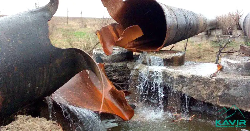
Damage caused by a water hammer
4. Water Hammer Analysis and Calculations
Water hammer analysis in pipelines is among the most complex yet fascinating challenges faced by engineers involved in pumping and transmission systems. The phenomenon arises from sudden changes in flow velocity and occurs over extremely short time intervals, which is why it is classified as a transient (unsteady) flow.
In steady state design, minor errors in estimating friction losses or minor head losses may result in insufficient pressure at the delivery point. However, under transient conditions, even the smallest miscalculation can lead to catastrophic system failure.
Transient flows can generate extremely high pressure fluctuations, intense vibrations, and loud—sometimes alarming—noise. In addition, cavitation is a common consequence. The severity of damage depends on several critical parameters, including:
- Installed hydraulic equipment (type of valves and control devices)
- Elastic properties of the pipe material and the fluid
- Presence of entrapped air within the pipeline
5. Water Hammer Mechanism and Pressure Waves
The most frequent cause of transients is the asynchronous startup or shutdown of a pump or the rapid actuation of a valve.
When a pump trips, a down surge (negative pressure wave) propagates from the pump toward the end of the pipeline with a velocity (a). This pressure wave effectively reduces the pressure of each individual point of the pipe by the amount ∆H.
Upon reflecting off the end of the line, it returns as an upsurge (positive pressure wave), significantly increasing the internal pressure of each point of the pipe by the amount ∆H.
Therefore, in one surge cycle which lasts for a period T, the pressure in all points of the pipe undergoes severe increases and decreases, which usually leads to the rupture or collapse of pipes and the infliction of serious damage on the water distribution infrastructure.
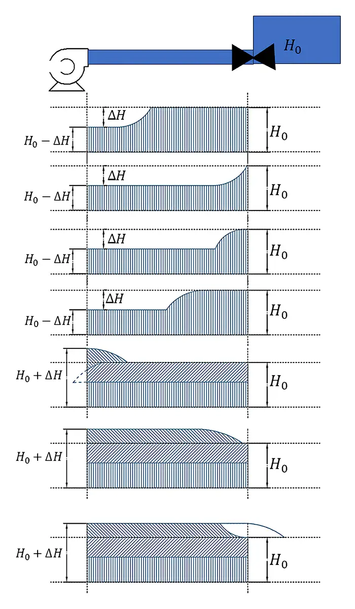
To analyze the water hammer phenomenon, it is necessary to determine the amount of pressure fluctuation (∆H), the wave period, and the wave propagation velocity (a).
Pro Tip: There is no simple formula or Excel file for water hammer calculations. Water hammer calculations are based on the principles of conservation of energy and conservation of momentum and the relevant formulas. Numerical calculations are performed using the Method of Characteristics based on elastic theory and are solved numerically using a computer and one-dimensional and two-dimensional differential equations within the desired boundary conditions.
6. Joukowsky Equation
In 1900, the Russian scientist Joukowsky established the fundamental equation for maximum transient pressure resulting from velocity differences (also known as the St. Petersburg formula):
ΔH=(α.ΔV)/g
Where:
- a: Pressure wave velocity (m/s)
- ΔV: Velocity change (m/s)
- g: Gravitational acceleration (9.81 m/s²)
Typical values of wave speed:
- Steel and ductile iron pipes: 800–1200 m/s
- PVC or HDPE pipes: 300–500 m/s
Wave Speed Calculating in a pipe (a)
The speed at which a pressure wave travels is not constant; it depends on the modulus of elasticity of the pipe and the compressibility of the fluid. The specialized formula used by engineers is:
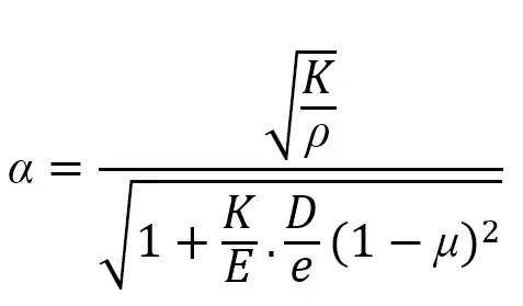
Where:
- a: Pressure wave propagation speed (m/s)
- D: Pipe diameter (mm)
- K: Fluid bulk modulus (N/m^2)
- μ: Pipe Poisson’s ratio
- E: Pipe modulus of elasticity (N/m^2)
- e: Pipe thickness (mm)
Time Cycle (T)
The critical time for a pressure wave to travel to the end of a pipe of length L and return to the source is defined as:
T=4L/a
Where L is the pipeline length (m).
When the wave begins at the pump with velocity a, a complete cycle lasts T=4L/a. The phenomenon continues until it dissipates through friction and energy loss as heat.
Understanding this time cycle is vital to determine valve closure timing and proper sizing of surge protection equipment.
7. Water Hammer Mitigation Methods
Since pressure variation directly depends on velocity change, most anti-surge systems are designed to control rapid velocity transitions.
Critical Scenario: Rapid Valve Closure
One of the most common causes of water hammer—especially in gravity pipelines—is rapid valve closure that halts flow abruptly. This action generates pressure waves that travel throughout the system until they reach hydraulic boundaries (valves, pumps) and reflect back, oscillating until the system stabilizes.
When the disc, gate, or ball of a valve closes suddenly, the water column’s momentum exerts enormous force on the valve closure, creating two simultaneous effects:
- Upstream: Sudden rise in pressure due to flow impact
- Downstream: Sharp pressure drop due to water column separation
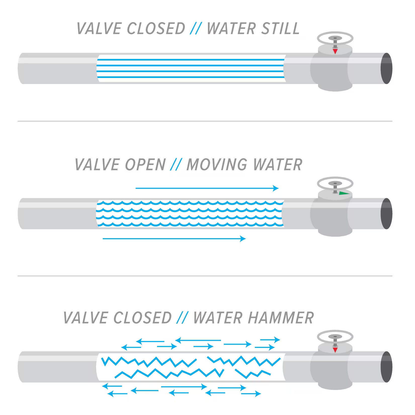
Downstream, the fluid continues its motion, creating a vacuum which may cause pipeline collapse. If the pipeline is sloped downward, this effect and its hazards intensify further.
Control of Valve Closure:
Valve closure timing has a major effect on maximum pressure. The final stages of valve closure (last 2–5%) are critical in determining surge magnitude. The best method to assess closure timing impact is to evaluate valve head loss characteristics using surge analysis software.
Vacuum Breaker Valves
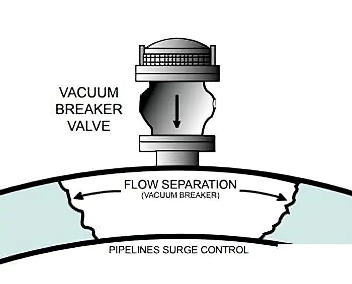
These valves are usually installed upstream of equipment generating high pressure drops. They come in various types—from simple spring-loaded models to complex high-end designs. When pressure falls below a certain threshold, the valve opens to allow air entry, preventing excessive vacuum formation.
Critical Scenario: Sudden Pump Shutdown
One of the most important causes of water hammer and high and low pressures in pressurized flows is the failure of the pump due to a sudden power outage. In this case, the amount of flow and velocity of the fluid inside the pipeline decreases (suddenly becomes zero), but due to the momentum of the liquid column, the fluid continues to move forward and causes a decrease in pressure behind it.
This pressure may decrease so much that it reaches the vapor pressure of the fluid and causes cavitation and separation of the water column, which will cause gradual corrosion of the inner wall of steel and cast iron pipes or crumpling of polyethylene pipes.
After a while, the flow velocity decreases due to friction and static pressure of the system and reaches zero. After this moment, the direction of movement reverses and the liquid flow towards the pump begins. At this moment, the check valve in the pump’s thrust line is usually closed and the pressure at the cavitation site increases, causing the fluid vapor to condense.
In this situation, the two separated liquid columns collide violently with each other. This collision of the two liquid columns creates very high pressures and sometimes causes serious damage to the pumping station equipment and pipeline.
To control this situation, the following equipment is used:
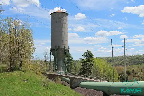
Atmospheric Surge Tanks
Atmospheric surge tanks prevent both positive and negative pressure surges. When pressure rises, the tank acts as storage, allowing water to flow into it. When pressure falls, the tank feeds water back into the line, stabilizing the system.
Types:
- One-way surge tank (OWST): Controls only negative pressures
- Two-way surge tank (TWST): Manages both positive and negative pressures
The two-way type is most effective for comprehensive surge control.
Pressurized Surge Tanks (Air Chamber / Surge Vessel)
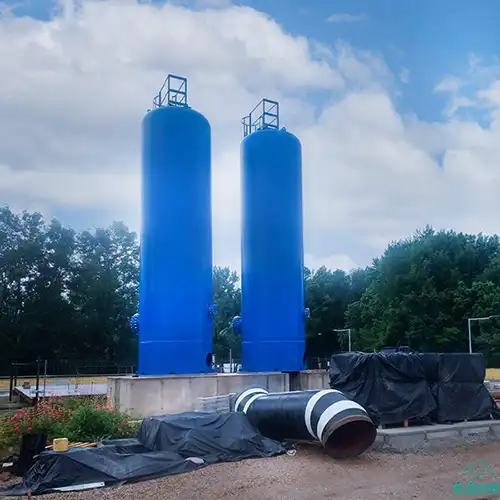
In pressurized surge tanks, compressed air is stored above water inside a sealed chamber. When pump shutdown causes pressure drop, the compressed air expands and pushes water into the pipeline. The degree of pressure reduction depends on the initial air volume and the isothermal process behavior.
As water is gradually released into the pipeline, flow velocity decreases more smoothly, preventing low-pressure conditions and column separation. When pressure rises, air compression absorbs the excess.
Such surge vessels are among the most reliable methods for controlling both positive and negative pressure surges, though they require compressed-air supply and periodic maintenance.
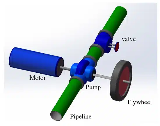
Flywheel
Since water column separation often results from the low rotational inertia of a pump, adding a flywheel between the pump and the motor can prevent rapid deceleration. By increasing the system’s moment of inertia following a power failure, the motor slows down gradually, significantly reducing the initial negative pressure wave.
Flywheels are relatively inexpensive, require minimal maintenance, and are suitable for pipelines shorter than approximately 2 km. However, due to the complexity and high cost of manufacturing and installation by original equipment manufacturers, along with their limited applicability, flywheels are not produced by domestic manufacturers, and their practical implementation is generally not recommended.
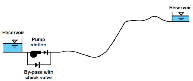
Pump Bypass Line
A bypass line connects the discharge header to the suction side via a check valve. In the steady-state, the pump discharge pressure keeps this check valve closed, and as soon as a negative surge is occurs, the check valve opens, allowing suction-side head to feed the discharge line. This prevents excessive pressure drop by maintaining flow and avoiding sudden velocity reduction.
This method has very limited application because it cannot work in pumps equipped with valves (when the water level on the suction side is lower than the pump). The pump bypass pipe can work in pumping stations where the water level on the suction side is on the pump and has a very low static head (less than a/Vg) because in pumping systems with higher head it can only cover a very small area from the beginning of the pipeline, and this method cannot be effective against pressure increases.
Double-Orifice Air Valves (Not Recommended)
Double-orifice air valves include a large and a small orifice. During a pressure drop, the large orifice opens to allow air intake into the pipeline; during a pressure rise, it closes, and the trapped air is released through the small orifice.
Although manufacturers recommend these valves to mitigate negative pressures, their performance during hydraulic transients is problematic. A large volume of air enters the pipeline rapidly, but its discharge through the small orifice is slow due to the very limited discharge area, causing air entrapment and hydraulic disturbances.
The trapped air must be gradually released under steady-state conditions. Due to air compressibility, accurate numerical modeling and analysis of these valves during transient events become complex and unreliable. Consequently, the use of double-orifice air valves to control negative pressures in water hammer conditions is generally not recommended and has very limited practical application.
Check Valves (Not Effective)
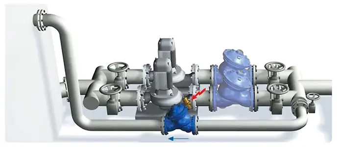
Installing a check valve at the pump discharge is essential to prevent backflow and reverse rotation of the pump after shutdown, which can cause severe mechanical damage. In short pipelines with high wave velocity, selecting a check valve with a rapid closure time is critical.
Although the installation of check valves at intermediate stations along the transmission line is sometimes proposed as a surge control measure, if downstream valves do not close faster than upstream ones, extremely high pressures—known as “hydraulic press”—can develop between adjacent check valves, posing a serious risk to the pipeline system. Therefore, this approach is not recommended.
Surge Relief Valves (SRV)
The most economical approach to reducing high pressure during water hammer in pumping stations is using surge relief valves.
A combination of spring-loaded check valves and SRVs at selected points ensures that during a surge event, check valves close rapidly while SRVs discharge excess pressure—protecting both pipelines and pumps.
For systems facing negative pressures, combining flywheels, spring-loaded check valves, and surge relief valves offers a cost-effective and comprehensive solution for positive and negative surge control.
8. Optimal Solution: A Technical Comparative Analysis
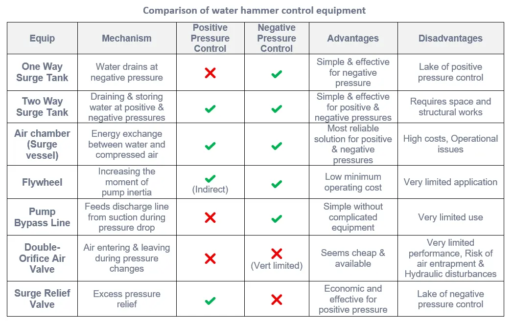
To select the best surge mitigation method, each device’s performance in controlling positive and negative pressure transients must be carefully evaluated. The comparison table below (referenced in the original source) shows technical differences among common surge control systems.
9. FAQ: Common Questions about Water Hammer
Does water hammer occur in plastic pipes (PVC/HDPE)?
Yes. Although flexible, these pipes have lower pressure ratings. Repeated hammer events cause material fatigue, bulging, and cracks. Negative pressures can crush HDPE pipes.
Is hearing a noise the only sign of water hammer?
No. “Silent transients” can occur—where pressure waves exceed material yield stress without audible sound, still causing damage.
Which software is best for water hammer analysis?
Professional designs typically use industry-standard tools such as Bentley HAMMER or AFT Impulse for accurate Joukowsky‑based transient modeling.
10. Professional Engineering Consultation
Effective surge management goes far beyond theoretical analysis—it requires practical experience in real projects.
Kavir Engineering Group has a proven record with more than 100 successful surge control projects and over 500 pumping station and transmission line designs.
Whether your project involves water, wastewater, or oil transmission, our team provides advanced engineering solutions to ensure system safety and structural integrity.
For customized surge analysis and design consultation, contact us.